| Section | Dimensions | Mass | Per meter of wall | ||||
| Width | Height | Thickness | Single pile |
Wall | Section modulus |
Bending Moment |
|
| e | h | t | W | I | |||
| mm | mm | mm | Kg/m | kg/m2 | cm3/m | KNm/m | |
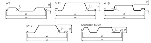
| M7 | 406 | 38 | 3.55 | 14.35 | 35.84 | 51.2 | 8.7 |
| M11 | 400 | 84 | 3.55 | 16.4 | 41 | 138 | 23.4 |
| M13 | 660 | 90.5 | 4.5 | 29.1 | 44 | 109 | - |
| M15 | 494 | 75 | 6 | 33.53 | 67.9 | 186 | 50 |
| M17 | 705 | 150 | 6.35 | 50.4 | 71.7 | 424 | 91.8 |
| Multilock 500/4 | 520 | 75 | 4 | 24.3 | 46.7 | 118.3 | 55 |
| GFI SEI | 500 | 75 | 6 | 33.8 | 67.7 | 206 | 62 |
Interlocking trench sheets M7 projects that are currently M11 under construction M13 or M15 are in the M17 planning stages at the Port, totaling $3.7 billion in investment. The minimum spacing between ground anchor bonded lengths should be the larger of three times the diameter of the bonded M7 length, or 5 feet. An individual knowledgeable about fall protection equipment, including the manufacturers recommendations and instructions for the proper use, inspection, and M11 maintenance; and who is capable of identifying existing and potential fall hazards; If smaller spacings are required to develop the required anchor design force, consideration M13 may be given to differing the anchor inclinations between alternating anchors. Projects include those in planning or design stages, under environmental review, and M15 those considered “shovel ready.”
LAANE categorized the projects as follows:Tie rods should be protected from corrosion by complete full-length M17 encapsulation and electrical isolation from the wall and structural anchor at the connections to these members. It has the authority to take prompt corrective action to eliminate those M 7 hazards; and is knowledgeable of the rules contained in this section regarding the erection, use, inspection, and maintenance of fall protection equipment and systems.
Trench sheet multilock 500/4 walls are generally GFI or SEI locked off against the wall at a load equal to 0.75 times the design force, T, of the anchor. Terminal improvement projects or demolitions taking place on Port land; Community-wide projects: All ground anchors for walls should be load tested with either a proof test, performance test or creep test. The maximum test load for an anchor should generally be 1.5 times the design force, T, of the anchor. M 11 A device that is used to couple (connect) parts of the personal fall arrest system and positioning device systems together. Higher lock-off forces M 13 may be considered in order to minimize wall movements or to develop higher frictional forces between the wall elements and the retained soil mass.
Public-benefit projects directly adjacent to the Port, but not M 15 related to goods movement, including the development of the San Pedro Waterfront and the Harry Bridges Buffer; Environmental Mitigation. It may be an M 17 independent component of the system, such as a carabineer, or it may be an integral component of part of the system (such as a buckle or D-ring sewn into a body harness, or a multilock 500/4 snap hook spliced or sewn to a lanyard or self-retracting lanyard). Projects intended to reduce environmental impacts related to Port activity through emissions reduction, preservation of wildlife or improving water quality. The area between the warning line system and unprotected sides and edges of the walking/working surface. Ground anchors GFI and SEI with strand tendons should be locked -off at a force which produces a stress in the strand of at least 0.50 fpu of the strand in order to ensure that the strand wedges at the tendon anchorage maintain a sufficient grip on the strand to preclude slippage.
Interlocking sheets and light piling are taking place sheet piles directly on Port property or in adjacent areas, and Transportation Improvements. The additional vertical distance a falling employee travels excluding lifeline elongation and free fall distance, before stopping, from the point at which the deceleration device M17 begins to operate. If this lock-off force can not be provided, alternative means of restraining the strand wedges should be provided. Projects intended to improve goods movement flow to and from the Port—such as roads, bridges and rail yards. MSE wall system design requires knowledge of short and long-term properties of the materials used as soil reinforcement as well as the soil mechanics which govern MSE wall behavior. Structural design of the wall facing may also be required.
Any mechanism, such as a rope grab, ripstitch lanyard, specifically woven M7 lanyard, tearing or deforming lanyards, automatic self-retracting lifelines/lanyards, etc., which serves to dissipate a substantial amount of energy during a fall arrest, or otherwise limit the energy imposed on an employee during fall arrest. MSE walls shall be designed for external stability of the wall system as well as internal stability of the reinforced soil mass behind the facing.
The Port of Los Angeles’ extensive infrastructure improvement programs have the potential to contribute to the region’s economic recovery. A vertical GFI or SEI sheet piles lifeline secured to an upper anchorage for the purpose of attaching a lanyard or device. But a policy is needed to ensure that this significant public investment translates into good jobs for local residents. Load refusal, breakage, or M15 separation of component parts. Load refusal is the point where the ultimate strength is exceeded. The multilock 500/4 design provisions light piling provided herein for MSE walls do not apply to geometrically complex MSE wall systems such as tiered walls (walls stacked on top of one M13 another with various offset distances of the front face) or walls with varying soil reinforcement length over the height of the wall.
City leaders and port officials recognize the importance of maximizing the economic development benefits of investment. In 2008, the Los Angeles City Council’s Trade, Commerce, and Tourism committee requested that Harbor Commissioners explore developing a “Construction Careers” policy, along the lines of the one adopted by the L.A. Community Redevelopment Agency that same year. It is M11 interlocking sheets measured as the distance between the location of an employee's body harness attachment point at the moment of activation (at the onset of fall arrest forces) of the deceleration device during a fall, and the location of that attachment point after the employee comes to a full stop.