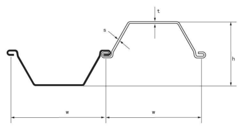
| Section | Dimensions | Sectional Area |
Mass | Moment of inertia |
Modulus of section |
|||
| Width | Height | Thickness | Pile | Wall | ||||
| w | h | t/s | ||||||
| mm | mm | mm | cm2/m | kg/m | kg/m2 | cm4/m | cm3/m | |
| SCU7 | 750 | 320 | 5 | 71.3 | 42 | 56 | 10725 | 670 |
| SCU8 | 750 | 320 | 6 | 86.7 | 51 | 68.1 | 13169 | 823 |
| SCU9 | 750 | 320 | 7 | 101.4 | 59.7 | 79.6 | 15251 | 953 |
| SCU11 | 600 | 360 | 8 | 131.4 | 61.9 | 103.2 | 19897 | 1105 |
| SCU12 | 600 | 360 | 9 | 147.3 | 69.5 | 115.8 | 22213 | 1234 |
| SCU13 | 600 | 360 | 10 | 162.4 | 76.5 | 127.5 | 24491 | 1361 |
| SCU16 | 650 | 480 | 8 | 138.5 | 71.3 | 109.6 | 39864 | 1661 |
| SCU18 | 650 | 480 | 9 | 156.1 | 79.5 | 122.3 | 44521 | 1855 |
| SCU20 | 650 | 540 | 8 | 153.7 | 78.1 | 120.2 | 56002 | 2074 |
| SCU23 | 650 | 540 | 9 | 169.4 | 87.3 | 133 | 61084 | 2318 |
| SCU25 | 650 | 540 | 10 | 187.4 | 96.2 | 146.9 | 69093 | 2559 |
Australia sheet piles SCU7 and SCU8 and SCU9 can be extremely hazardous in Townsville. Loads from any appurtenances attached to the facing elements shall be considered. Falls from elevation are a major cause of SCU7 injuries in the construction industry. Above the wall, slopes should be graded to drain and should be SCU 9 protected with vegetation.
Washington DOSH regulations require you to evaluate your worksite to identify fall hazards. On all but shallow slopes, SCU8 intercepting ditches or drains should be considered.You must then eliminate or control the fall hazards you identify.In the design of SCU 8 concrete, steel and timber SCU 11 facing elements the locations of the connected soil reinforcement are considered support locations in resisting the basic design SCU9 horizontal load. If falls hazards of 10 feet or more exist, you must provide a SCU 7 written plan which identifies. If the area above the wall is level, adequate provision for disposal of runoff by grading, paving and/or drains must be made.
SCU 7 SCU 8 and SCU 9 will use to eliminate and control Victoria . Additionally, many state highway departments have prepared standard Bin-Wall specifications, which may be referenced.The minimum SCU13 specified compressive strength, f´c , for concrete facing elements equals 4000 psi.Correct procedures for assembly, maintenance, inspection, an disassembly of fall protection systems used o Correct procedures for handling, storage, and securing of tools and materials.At the front of the wall, any SCU11 condition that allows ponding of water and SCU 12 subsequent softening of material under the toe of the wall should be avoided. The general specification will ensure SCU12 quality and workmanship.The minimum distance from the top or bottom of a facing element to a level of soil reinforcement equals 5 inches.
The method of providing overhead protection to the method for prompt, safe removal of injured workers.The maximum SCU11 vertical spacing of soil reinforcement connected to the facing elements equals 30 inches. Efforts to ensure that the SCU12 backfill material has a bearing capacity that is not adversely affected by excess moisture will be advantageous and less costly in the long SCU 13 run. Timber facing elements shall not be used to support a traffic barrier support slab.
SCU 11 SCU 12 and SCU 13 allows heavy rains to saturate the Perth backfill in and behind the wall should be avoided. Training methods for the employees working on the jobsite. The fall protection work plan must be specific to the work SCU13 site.Loads from any appurtenances attached to the facing elements shall be considered.
Sheet piling SCU11 SCU12 or SCU13 must be available on the work site for review. The documentation of training must be available on the work site for review. How do I write the plan.Timber facing elements shall be structurally designed in accordance with Section 13 using the working stress design method. Use the attached template to assist you.
Have a “competent employee” complete the template to make it work site specific Customize the template as needed by adding missing SCU9 information and/or deleting unnecessary information. The basic service load shall be a distributed horizontal load acting on the entire back face of the face element the resultant of which is equal to the sum of the, Ta , values of the soil reinforcement connected to the face element. The plan form and individual site plans must accurately describe the SCU8 conditions at your worksite and the methods you will use. The location of the resultant of this distributed load shall be at the location of the resultant of the, , values of the same soil reinforcement.
A compliance officer will, in addition to ensuring that you plan contains all the required elements; determine if it describes SCU7 what you actually do. If it does not, you may be subject to citation and monetary penalty!